WARNING: PC parallel port can be damaged quite easily if you make mistakes in the circuits you connect to it. If the parallel port is integrated to the motherboard (like in many new computers) repairing damaged parallel port may be expensive (in many cases it it is cheaper to replace the whole motherborard than repair that port). Safest bet is to buy an inexpensive I/O card which has an extra parallel port and use it for your experiment. If you manage to damage the parallel port on that card, replacing it is easy and inexpensive.
NOTE: The I/O port level controlling details here has proven to work well with parallel ports on the PC motherboard and expansion cards connected to ISA bus. The programming examples might not work with PCI bus based I/O cards (they can use different hardware and/or I/O addresses, their drivers make they just look like parallel ports to "normal" applications). The programming examples do not work with USB to parallel port adapters (they use entirely different hardware, their drivers make them to look like normal parallel port to operating system "normal" applications).
DISCLAIMER: Every reasonable care has been taken in producing this information. However, the author can accept no responsibility for any effect that this information has on your equipment or any results of the use of this information. It is the responsibly of the end user to determine fitness for use for any particular purpose. The circuits and software shown here are for non commercial use without consent from the author.
How to connect circuits to parallel port
PC parallel port is 25 pin D-shaped female connector in the back of the computer. It is normally used for connecting computer to printer, but many other types of hardware for that port is available today.
Not all 25 are needed always. Usually you can easily do with only 8 output pins (data lines) and signal ground. I have presented those pins in the table below. Those output pins are adequate for many purposes.
pin function
2 D0
3 D1
4 D2
5 D3
6 D4
7 D5
8 D6
9 D7
Pins 18,19,20,21,22,23,24 and 25 are all ground pins.
Those datapins are TTL level output pins. This means that they put out ideally 0V when they are in low logic level (0) and +5V when they are in high logic level (1). In real world the voltages can be something different from ideal when the circuit is loaded. The output current capacity of the parallel port is limited to only few milliamperes.
Here is a simple idea how you can connect load to a PC parallel port data pins.
Dn Out ------+
|+
Sourcing Load (up to 2.6 mA @ 2.4 v)
|-
Ground ------+
This is not the only way to connect things to a parallel port.
The parallel port data pins are TTL outputs, that can both sink and source current. In ordinary parallel port implementations the data outputs are 74LS374 IC totem-pole TTL outputs which can source 2.6 mA and sink 24 mA.
Regular TTL outputs basically consist of a two "stacked" transistor in series between +5 volts and ground, with the output coming from the connection between them. This is called a "totem pole output". At any given time one of these transistors is conducting and the other is not. To pull the output "high", the transistor from +5 to the output conducts (H), which "sources" positive current from the output to ground (that is, an external device between the output and ground will get power). To pull the output low, only the lower transistor (L) conducts, "sinking" current to ground; an external device between +5 volts and the output can be energized.
+5
/ |
---H on V
\ -->
|________ TTL output on = 1 = high, "sourcing" current
| out \
/ / |
---L off \ V
\_________/
Gnd
+5_________
/ \
---H off / |
\ \ V
|________/ TTL output off = 0 = low, "sinking" current
| <-- out
/
---L on |
\ V
Gnd
The outputs are designed so that they give at least 2.4V at 2.6 mA load. This 2.6 mA figure is for ordinary LS-TLL circuits used, the LSI implementations used in many computers can give more or less. For example quite popular (few years ago) UM82C11-C parallel port chip can only source 2 mA.
Simple current sinking load connection:
Dn Out ------+
|+
Sourcing Load (up to 2.6 mA @ 2.4 v)
|-
Ground ------+
When taking current from PC parallel port, keep the load low, only up to few milliamperes. Trying to toke too much current (for example shorting pins to ground) can fry the parallel port. I have not killed any parallel port (yet) in this method, but I have had in cases where too much load has made the parallel port IC very hot. Be careful.
If you have an external +5 volt supply, you have another option for connection: use the Data Out pins to sink up to 24 mA from your +5 volt supply. This can be made with a circuit like this:
+------------------------------- (+5 v)
|+
Sinking Load (up to 24 mA @ 4.2v)
|- Power Supply
Dn Out ------+
Ground -------------------------------------- ( Gnd)
The load gets power then you have external +5V on and the printer port data pin set to 0. This circuit gives you capability of of driving more current than the "sinking" approach. You need to be careful with this circuit, because with this circuit you can easily fry the parallel port if you do things wrong. My advice is to be very careful with this type of circuit and make sure that the external +5V power supply gets turned off when computer gets turned off (all printer ports might not like getting +5V though the load to printer port when they are not powere). The most convient source "external +5V" might be from same other port on your PC (USB, joystick, keyboard/mouse etc. port).
I have used mostly "sinking" type circuits and this article is concentrated on using them.
Simple LED driving circuits
You can make simple circuit for driving a small led through PC parallel port. The only components needed are one LED and one 470 ohm resistors. You simply connect the diode and resistor in series. The resistors is needed to limit the current taken from parallel port to a value which light up acceptably normal LEDs and is still safe value (not overloading the parallel port chip). In practical case the output current will be few milliampres for the LED, which will cause a typical LED to somewhat light up visibly, but not get the full brigtness.

Then you connect the circuit to the parallel port so that one end of the circuit goes to one data pin (that one you with to use for controlling that LED) and another one goes to any of the ground pins. Be sure to fit the circuit so that the LED positive lead (the longer one) goes to the datapin. If you put the led in the wrong way, it will not light in any condition. You can connect one circuit to each of the parallel port data pins. In this way you get eight software controllable LEDs.
The software controlling is easy. When you send out 1 to the datapin where the LED is connected, that LED will light. When you send 0 to that same pin, the LED will no longer light.
Here are two photos of circuit above:
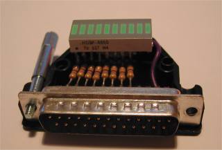
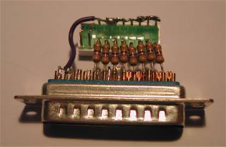
Pn those circuits I have wired the ground wire only to one ground pin (it works also well, you can use any of the ground pins).
No comments:
Post a Comment